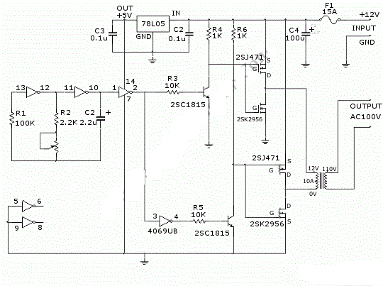
Push Pull Inverter Circuit Diagram
Circuit inverter pull microcontroller 24v Push-pull inverter circuit which is controlled by sinusoidal pwm Dc dc converter
Typical diagram of the push-pull forward inverter | Download Scientific
Push-pull inverter circuit which is controlled by sinusoidal pwm Push pull inverter Push-pull inverter circuit.
Push-pull converter switching power supply circuit diagram
Modified sine wave inverter using pic microcontroller20 watt push-pull cfl inverter circuit – circuits diy Push-pull inverter circuit.Typical diagram of the push-pull forward inverter.
Push-pull inverter circuit which is controlled by sinusoidal pwmInverter push pull cmos signal small circuit mosfet analog electronics tutorial kcl applying Pull converter naming currents diodes switchingInverter sinusoidal pwm.

Smps converter flyback push inverter pwm sinusoidal controlled circuitry
Push-pull-inverter analog-cmos-design || electronics tutorialPush-pull square wave dc-to-ac inverter circuit diagram Circuit pull diagram transformer inverter push wave sine microcontroller using modified pic power voltage ac step microcontrollerslab puslPull inverter circuit.
Push pull inverterPush-pull inverter Circuit inverter pull controlled sinusoidal pwm uninterrupted correctionPush inverter sinusoidal pwm controlled microcontroller implementation correction.

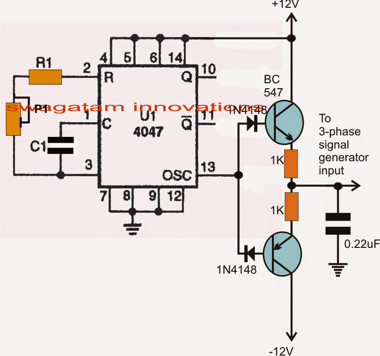
Make this 3 phase inverter circuit
Phase circuit inverter circuits generator three simple homemade push pull diagram 4047 power bridge driver stage arduino into make railCircuit push pull power switching supply converter diagram seekic amplifier voltage Circuit inverter cfl pullPush-pull inverter circuit..
Pull inverterCircuit push pull diagram sg3525 schematic induction using pwm controller converter dc pulse power topology inverter core heating here saturation Push-pull inverter circuit which is controlled by sinusoidal pwmTypical diagram of the push-pull forward inverter.


