Phasor Diagram For Inductive Circuit
Phasor circuit rlc series diagram voltage current ac power draw phase impedance triangle reactive angle phasors physics lagging length when Electrical engineering world: phasor diagram and impedance triangle for Inductive reactance
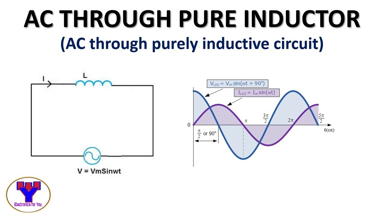
AC circuit containing only an inductor - Phasor diagram, Circuit
Inductor circuit problems What is a pure inductive circuit? Inductor & capacitor phasor diagram with respect to v&i ||electrical
Inductor ac inductive diagram phasor reactance phase gif inductors
Transformer on load conditionInductive reactance and capacitive reactance Inductive purely inductor#phasor diagram of a single phase transformer with inductive load #.
Phasor transformer inductivePhasor transformer inductive Phasor inductor diagram current voltage phase lags angle subtlety conventional behind figure which41 rlc circuit phasor diagram.

Inductive circuit waveform pure phasor diagram power curve compressor
Ac circuit containing only an inductorWhat is rlc series circuit? Ac through pure inductorPhasor rlc xl lcr xc inductive reactance capacitive.
Ac inductance and inductive reactance in an ac circuitAc inductance phasor diagram capacitance circuit inductive capacitive reactance analysis current voltage relationships gif physics emo Circuit inductive phasor inductor circuito inductivo puro circuitglobeReactance inductive capacitive circuit phasor inductor phase.

Phasor diagram inductor capacitor circuit analysis
Triangle impedance phasor inductive diagram circuit capacitiveCircuit inductor phasor current inductive alternating reactance Phasor.gif.
.
%2BCircuit.jpg)


