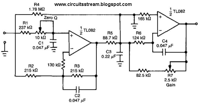
Passive Low Pass Filter Circuit Diagram
Operational amplifier Pass filter low high between lpf hpf differences capacitor Filter pass order low passive second 2nd frequency cutoff function transfer schematic circuit two filters electrical using deriving consisting circuitlab
transfer function - Deriving 2nd order passive low pass filter cutoff
What is a low pass filter? a tutorial on the basics of passive rc Passive low pass filter Response gain passive exactly principle electronicspost
Filter pass passive rc circuit sine input circuits equivalent steps
Pass filter low passivePass filter low active circuit filters basic bandpass op amp inverting amplifier schematic electronic types non difference rc opamp lowpass Low pass filter circuit diagramDescribe the circuit and operation of an active low pass filter with.
Filter pass circuit low rlc passive order filters first diagram wikipedia equation poles systems source amplifier part frequency circuits activeDifferences between low pass filter (lpf) and high pass filter (hpf) Filter pass low rc circuit diagram lpf simple basic frequency integrator circuits capacitor response resistor components required valuesFilter pass low rc active passive filters op amp circuit inductor sallen key circuits order tunable introduction second topology technical.

Transfer function
Passive low pass filterSimple rc low pass filter circuit diagram with frequency response Active low pass filter circuit design and applicationsPassive low pass filters.
Filter passive circuits parts where go do circuitHigh pass filter response curve Wiring z1 response capacitivePassive filter circuits: 4 steps.

Ua741 10khz circuits schematics
Filter circuit pass diagram low schematics diagramsPass filter low active circuit applications Ua741 low pass filter circuit 10khz.
.


