Ir2110 Inverter Circuit Diagram
The application of ir2110 in three phase bridge motor drive circuit Ir2110 inverter Ir2110 mosfet & igbt driver ic
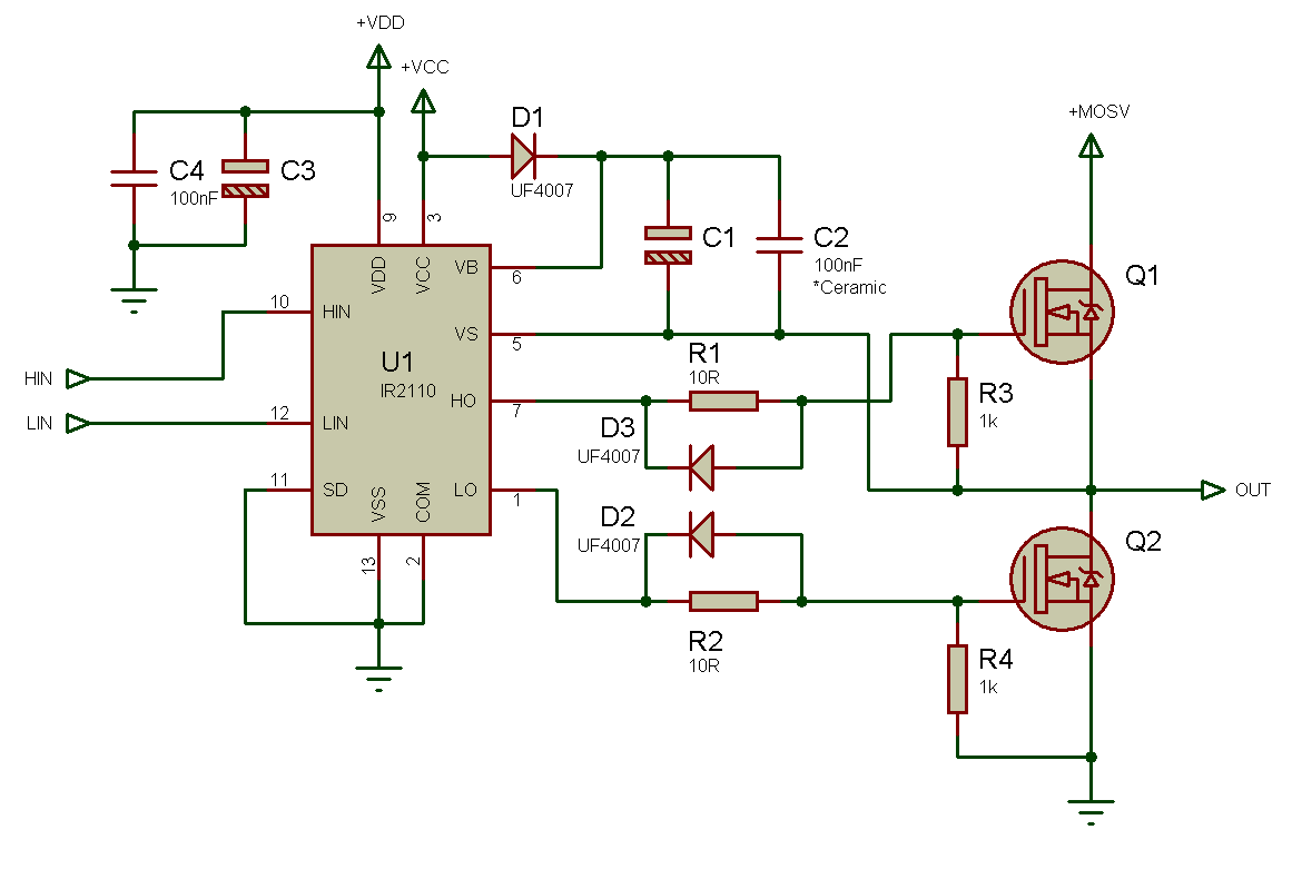
IR2110 drive circuit with level clamp function - Basic_Circuit
Pure sine wave inverter using ir2110 Circuit ir2110 power stage based Using the high-low side driver ir2110
Circuit ir2110 phase motor three application bridge diagram drive seekic electrical equipment ic
Ir2110 mosfet driver circuit igbt ic choose boardInverter sine wave circuit ir2110 pure using thanks Ir2110 circuit clamp function drive level seekic basic diagramIr2110 pwm 16khz 220v.
Ir2110 drive circuit with level clamp functionBridge ir2110 driver using circuit diagram gate mosfet make inverter microcontrollerslab drive high mosfets drivers used two How to make h bridge using ir2110Ir2110 based power stage circuit.

Ir2110 full bridge inverter drive circuit 12v power supply logic level
.
.


