Edge Triggered Flip Flop Circuit Diagram
Negative edge triggered jk flip flop circuit diagram Flop triggered flops latch latches triggering response chegg inputs Flip flop edge triggered circuit trigger logic approach negative using gates digital stack
negative edge triggered jk flip flop circuit diagram | All About Circuits
Negative edge triggered d flip flop circuit diagram Flip flop edge triggered positive timing jk diagram output inputs digital sketch shown logic clk below question solved Flip discrete flop circuit using flops diagram transistors hackaday explanation io
Triggered flop
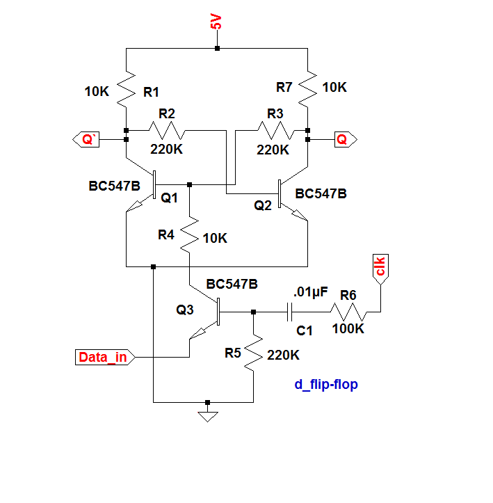
Digital logicFlip flop edge triggered type circuit nand positive input flipflop clock gates digital circuits there create between signal logic way Solved for a positive-edge-triggered d flip-flop with inputsWhat is a d flip-flop ??? (using discrete transistors).
Digital logicEdge-triggered d flip-flop behavior Flop flip edge triggered circuit circuits simulation simulatorNegative edge triggered d flip flop circuit diagram.

Solved referring to the negative-edge triggered d flip-flop
Negative flip flop triggered solvedStorage elements : flip flops Flip flop 7474 triggered negative jk resetEdge-triggered d flip-flop.
Flip flop edge triggered behaviorFlip flop circuit diagram edge triggered block table blocks sequential unit building upscfever truth flops elements storage logical organization computer .


