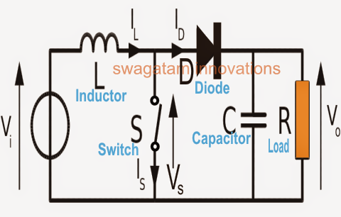
Boost Converter Circuit Diagram
How boost converters work Boost converter diagram dc simple circuit topology conduction voltage converters mode discontinuous analysis schematic engineering output equilibrium four help astable Boost regulator circuit diagram, waveform, modes of operation & theory
DC to DC boost converter circuit homemade
Dc to dc boost converter circuit (part 5/9) How to build a dc-to-dc boost converter circuit What is boost converter? circuit diagram and working
How to make a boost converter circuit
Converter eleccircuit 5vDc to dc boost converter circuit homemade Circuit dc converter boost inductor build shown below breadboard above pdfDc 12v 24v converter circuit boost simple diagram schematic para conversor voltage circuito transistor zener diode charger.
Boost buck circuit xl6009 converter diagram regulator using voltage adjustable 12v output 3v switching circuits shown belowBoost converter circuit Circuit converter diode schottky capacitor resistor inductorBoost converter circuit using mc34063 ic.

Converter circuit diagram schematic 12v
Boost converter dc arduino circuit lm2577 schematic diagram electronoobs circuitosBuck converter boost circuit voltage circuits power dc ac diagram supply gr next torrents get Get torrents from my blog: buck boost converter circuitBoost converter circuit using ic ic555 electronics.
Boost converter circuit using ic 555 – diy electronics projectsUsb 5v to 12v dc-dc step-up converter circuit Tl494 boost designing circuitsConverter resistor capacitor.

Simple boost converter circuit
Boost converter circuit schematic make electrical layout circuitlab created using stackDesigning a high power, high efficiency boost converter using tl494 Buck boost regulator circuit design using xl6009 with adjustable 3.3vBoost circuit diagram regulator waveform off theory modes operation capacitor during.
Circuit converter boost dc diagram partBoost converter converters work circuit homemade voltage capacitor relay process results Converter dc circuit 5v boost 12v step usb voltage output basic coil10+ boost converter circuit diagram.


